The Diesel Stop banner
21 - 40 of 88 Posts
Very Easy……. Amps = watts divided by volts

👍
It is quite easy but 99% of vehicle owners and others out there have no idea of how to do it. Not knowing the amperage of a circuit is very dangerous and the cause of quite a few fires. No different than the home owner who keeps on plugging in Christmas lights until the fuse starts to blow and they have no idea why.
Image
 
14 gauge (#14 wire) is rated 15 Amps. I think that is what you meant to write. There is no 15 gauge wire. Yes, an extension cord has the advantage of protecting the wires from the weather.
Just on my second cup of coffee
 
One other thing that might be useful……either a rocker switch with lights when powered on…….or…….an LED indicator lamp wired to the #87 terminal of the relay, so you know the rear pod lights are on - should you forget or bump the switch on during daylight hours. I went with the LED as a visual reminder.
 
  • Like
Reactions: NaiveRancher
Also….. once you know the amperage draw of the pods, check the resistance drop for your length of run and choose the correct size wire gauge: (larger is OK…..but not smaller)

chart below:

Image


Also, and often misunderstood, resistance drop is the length of both legs of the circuit, positive and negative. Most people are way undersized on their wires.

I learned a lot on my camper build.

Image
 
This is my preferred voltage resistance chart which is actually for the American Boat and Yacht Council (ABYC)

Image


This is your watt to amp conversion given both batteries at rest and with the truck running:

Image


Image


So we’ll round to 5 amps, since you may be using the pods with the truck not running.

I’m guessing 25’ from source to LED pods (depending on relay or not) so 25 X 2 =50’

here are the two wires sizes (above red lines) depending on critical or non critical……. (I almost always use the “critical table” in the chart.

Image


You’ll have to double check your components, from battery to switch to pod, or larger wire to relay, and then length of run to the pods. Harbor freight sells 10 gauge extension cords but make sure it is copper and not copper clad (you don’t want that) and their specifications from the manufacturer would not list it.
I bought my 10 gauge extension cords from our Farm and Home supply store and they were pure copper (a few dollars more) but well worth it.

Good luck Jamie👍
 
  • Like
Reactions: NaiveRancher
Discussion starter · #28 ·
One other thing that might be useful……either a rocker switch with lights when powered on…….or…….an LED indicator lamp wired to the #87 terminal of the relay, so you know the rear pod lights are on - should you forget or bump the switch on during daylight hours. I went with the LED as a visual reminder.
good call thanks Glen
 
Discussion starter · #29 ·
Also….. once you know the amperage draw of the pods, check the resistance drop for your length of run and choose the correct size wire gauge: (larger is OK…..but not smaller)

chart below:

View attachment 191557


Also, and often misunderstood, resistance drop is the length of both legs of the circuit, positive and negative. Most people are way undersized on their wires.

I learned a lot on my camper build.

View attachment 191558
10-4 thanks for the info. I do understand alot of this. I run electrical for high pressure breathing air compressors i am installing, so i have a decent understanding of the relationship between voltage, amps and wire size, as well as run length. However, the relays and switches and diodes, and especially 12V automotive wiring, I am brand new to. I have only really had AC experience, very little DC
 
Discussion starter · #30 ·
This is my preferred voltage resistance chart which is actually for the American Boat and Yacht Council (ABYC)

View attachment 191559

This is your watt to amp conversion given both batteries at rest and with the truck running:

View attachment 191560

View attachment 191561

So we’ll round to 5 amps, since you may be using the pods with the truck not running.

I’m guessing 25’ from source to LED pods (depending on relay or not) so 25 X 2 =50’

here are the two wires sizes (above red lines) depending on critical or non critical…….

View attachment 191562

You’ll have to double check your components, from battery to switch to pod, or larger wire to relay, and then length of run to the pods. Harbor freight sells 10 gauge extension cords but make sure it is copper and not copper clad (you don’t want that) and their specifications from the manufacturer would not list it.
I bought my 10 gauge extension cords from our Farm and Home supply store and they were pure copper (a few dollars more) but well worth it.

Good luck Jamie👍


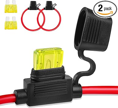
Thanks Glen. So it sounds like even though my lights will only draw 5 amps, I will want to run at least 10 gauge wiring (because of the assumed length), run from the battery to the switch (with a 15A inline fuse between the two), then run from the switch to the lights. Does this sound correct? Will the fuse get both the positive and negative wires run through it?
 
Discussion starter · #31 ·
I would just purchase a 15 ga extension cord down at the local hardware store. Then head over to a auto parts store and get the fuse holder and associated wire eyes that will be needed to connect the wire to the positive battery. I believe that your 2001 has a fender mounted relay where the battery cables terminate, you can connect the wires at this spot.


Then either just get a single pole switch at the parts store that you will need to either drill a hole in your dash or get one with a mounting bracket to attach to the dash.
thanks bud. I know where my positive cable is going to route and connect now, but where do i start and end the negative cable?
 
Discussion starter · #32 ·
How does this switch look to you guys? It is an SPST switch with a cover to prevent accidental bump and a built in LED

 
Discussion starter · #33 ·
I would just purchase a 15 ga extension cord down at the local hardware store. Then head over to a auto parts store and get the fuse holder and associated wire eyes that will be needed to connect the wire to the positive battery. I believe that your 2001 has a fender mounted relay where the battery cables terminate, you can connect the wires at this spot.


Then either just get a single pole switch at the parts store that you will need to either drill a hole in your dash or get one with a mounting bracket to attach to the dash.
Hey Bugman, should that fender mounted relay be on the driver side or passenger side?
 
On the relay I don't know since my 96 has it on the passenger side and with somewhere in the 2000 I believe that they eliminated it. Just trace out the positive cable coming off of the battery and see if it terminates somewhere and connect at that spot.

The ground really doesn't matter since you can pick it up off of the frame, if you want to connect one of the wires in the cord to a ground near the spot that you connect the positive that is fine also.

I also don't know if your year of truck has any pass through connectors on the firewall. If not just run the cord into the cab using the black wire as the power feed to the switch. Then come back out on the white wire. More than likely you'll cut the cord. If it is on the cab side or the light side you'll have to decide. Personally I would run the complete cord from the switch to the lights, but intercept it before it goes through the firewall to connect the battery power.

The switch is all up to you on what you like and what to install.
 
Discussion starter · #35 ·
On the relay I don't know since my 96 has it on the passenger side and with somewhere in the 2000 I believe that they eliminated it. Just trace out the positive cable coming off of the battery and see if it terminates somewhere and connect at that spot.

The ground really doesn't matter since you can pick it up off of the frame, if you want to connect one of the wires in the cord to a ground near the spot that you connect the positive that is fine also.

I also don't know if your year of truck has any pass through connectors on the firewall. If not just run the cord into the cab using the black wire as the power feed to the switch. Then come back out on the white wire. More than likely you'll cut the cord. If it is on the cab side or the light side you'll have to decide. Personally I would run the complete cord from the switch to the lights, but intercept it before it goes through the firewall to connect the battery power.

The switch is all up to you on what you like and what to install.
Thanks for the help bud. Just so i understand, there will be 3 wires in the extension cord (Hot, Neutral, Ground). Hot Wire - I will run the hot from the battery/relay to the switch, putting the 15A fuse between them, then from the switch, I run the hot straight to the red wire on the lights. Neutral Wire - I will use this as the negative wire that connects to the black wire on the lights. But where does the neutral connect at the beginning under the hood? Ground Wire - I can ground it under the hood and also at the rear on the frame?
 
Your whole truck, frame, body, and any metal is a ground. This is why any voltage measurements are taken to a grounded piece of metal. For the most part the only time that you need to supply a ground is when there is plastic involved in the part that you are mounting the light to since plastic doesn't conduct electricity.

Technically you only need a single wire to the lights that has power on it. Then on the lights you just ground one of the light wires to a mounting bolt for the light. If you want to your can just ground one of the wires anywhere near where you connect into the battery power and then connect that wire to the second wire on the lights.
 
  • Like
Reactions: NaiveRancher
If adding a relay you are only concerned with 30, 87, 86, 85…….if there is a 87A it won’t be used.

relays can be found with both 4 and 5 terminals. Most of the auto parts stores have them (30A relays - very popular)

30- power from battery
87- NO, power to accessory
86- switch power (+) (coil)
85 - ground (-) (coil)

technically speaking 86 & 85 can be switched to operate the coil, which in turn closes 87 until the power to the coil is dropped and 87 becomes NO (normally open) again. However, most of the time 86 is + and 85 is -

then the accessory that is being powered has a ground of its own, whether you run a dedicated wire or use the chassis. I will add that 99% of the time when there a problems with a 12V circuit it is normally a grounding issue (especially when chassis ground)
 
  • Like
Reactions: NaiveRancher
Discussion starter · #38 ·
If adding a relay you are only concerned with 30, 87, 86, 85…….if there is a 87A it won’t be used.

relays can be found with both 4 and 5 terminals. Most of the auto parts stores have them (30A relays - very popular)

30- power from battery
87- NO, power to accessory
86- switch power (+) (coil)
85 - ground (coil)

technically speaking 86 & 85 can be switched to operate the coil, which in turn closes 87 until the power to the coil is dropped and 87 becomes NO (normally open) again. However, most of the time 86 is + and 85 is -

then the accessory that is being powered has a ground of its own, whether you run a dedicated wire or use the chassis. I will add that 99% of the time when there a problems with a 12C circuit it is normally a grounding issue (especially when chassis ground)
thanks Glen, but im not gona be running a relay. Im just gona go from battery to switch to lights
 
Discussion starter · #39 ·
Your whole truck, frame, body, and any metal is a ground. This is why any voltage measurements are taken to a grounded piece of metal. For the most part the only time that you need to supply a ground is when there is plastic involved in the part that you are mounting the light to since plastic doesn't conduct electricity.

Technically you only need a single wire to the lights that has power on it. Then on the lights you just ground one of the light wires to a mounting bolt for the light. If you want to your can just ground one of the wires anywhere near where you connect into the battery power and then connect that wire to the second wire on the lights.
Ok thank you, that clears it up. Run hot wire from battery to switch then to red wire on lights. Ground wire grounded under hood near battery and run straight to black wire on lights. The inline fuse holder and switch are only connected to the circuit by the hot wire. Does this sound right?
 
Now you got it
 
21 - 40 of 88 Posts